This chapter describes how objects can be used and interconnected.
Contents
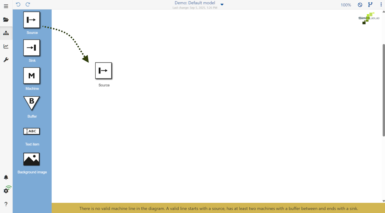
To add an object from the toolbox to the modeling area, simply drag and drop the desired object from the toolbox to any position in the modeling area (see Figure 1).
A info message is displayed at the bottom of the modeling area, as long as there is no valid machine line.
 s
s
Figure 1 - Adding objects to the modeling area
To copy an existing object, the desired object must first be selected with the mouse. Copying and pasting objects is also possible between several alternatives of the same project
The selected object can then be copied and pasted using one of the following options:
•Using the key combination [CTRL] + C and [CTRL] + V
•By clicking on the desired object, then holding down the [CTRL] key and dragging the object to another location
To select an object, simply click on the desired object with the mouse. You can also select several objects by holding down the [CTRL] key.
By holding down the mouse button for longer ("long click") a frame can be drawn up to mark serval objects (see Figure 2).
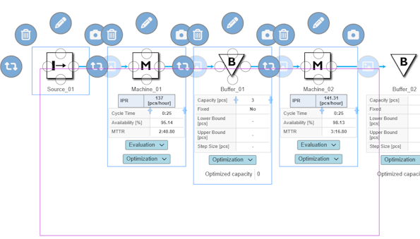
Figure 2 - Frame to mark multiple objects
Clicking on the |
|
icon the selected object can be parameterized via the sidebar. Additional information on object parameters can be found in chapter Parameterizing objects. |

Objects can be connected to each other via connecting lines. Each object from the Toolbox has four possible connection points, marked by a circle (see Figure 3).
A connection to another object can be established by clicking and holding down the left mouse button. The connection automatically docks to one of the four possible connection points of the target object.
The possible connections for an object are indicated by a green frame in the modeling area. By clicking on the connections, a ring menu appears which can be used to either delete or edit the connection.
In addition to a description, text alignment, routing and layout of the link can be edited in the side menu. Also a text can be stored in the comment field, which appears in the modeling interface as a tool tip.
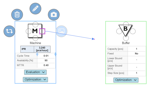
Figure 3 - Connecting two objects
© SimPlan AG - Hanau District Court, Commercial Register (Part B) 6845 - info@simplan.de - www.simplan.de/en