This chapter gives an overview of the modeling surface of the application. Figure 1 shows an overview of the modeling surface. The areas marked by numbers are explained in detail below.
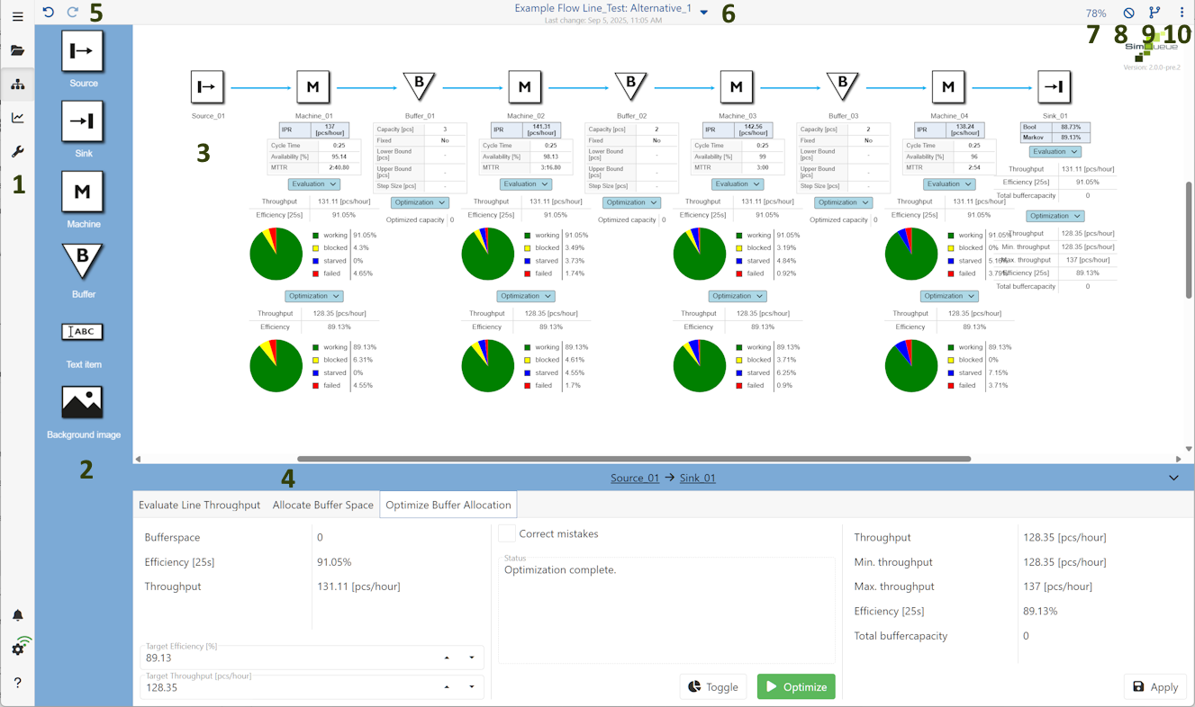
Figure 1 - Modeling surface
On the left side of the application there is the menu. Details about the menu can be found in the chapter Menu.
The toolbox contains a variety of objects. These can be dragged to the right onto the modeling surface by Drag’n’Drop to create a model.
The largest space of the application is available for modeling. Models can be created and managed here.
A description of the individual objects and how to use them can be found in the chapters Using objects and Parameterizing objects.
It is possible to zoom in on the modeling surface by holding down the [CTRL] key and moving the mouse wheel at the same time.
In the tablet or smartphone version, this functionality can be accessed via the standard zoom gesture.
The area below the modeling surface is used to evaluate and optimize the created models. Details and settings for those evaluations and optimizations can be found in the chapter Calculations and evaluations.
These two buttons can be used to undo or repeat actions that have been performed, such as inserting objects. Changes to parameter settings are not affected by this action.
The name of the currently selected project and the currently selected alternative is displayed here ("Project name": "Alternative name"). The time of the last change in the modeling interface is always displayed below.
Via the dropdown, the project name can be edited or exported, the project can be uploaded to the server and images can be exported, see figure 2.
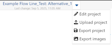
Figure 2 - Project settings and export
By clicking on the percentage value, different zoom settings can be accessed.
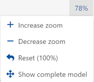
Figure 3 - Zoom settings
With this button, selected elemets of the dropdown can be hidden in the modeling area.
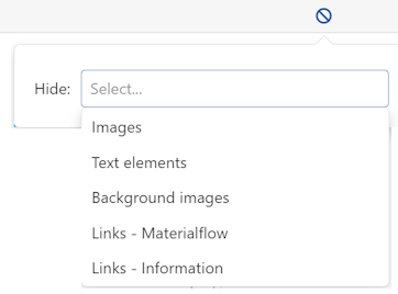
Figure 4 - Hide elements
When clicking the button |
|
the alternatives side bar opens, where alternatives can be created and managed. Details can be found in chapter Creating and organizing alternatives. |
The button |
|
opens a dropdown for different settings for the modeling surface, explained below. |
Figure 5 - Settings modeling surface |
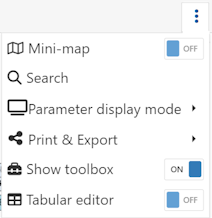
Mini-map
This button can be used to show or hide an overview window (mini map) that helps to keep an overview of the entire modelling, especially for larger projects.
Search
By clicking on the magnifying glass icon, objects can be searched for via a dialog. Figure 6 shows the dialog with the drop-down menu open, which contains all the objects used on the modeling surface.
As soon as an element has been selected and the search has been started via the "Search" button, the corresponding element is then selected on the modeling surface and the view is centered on the respective object.
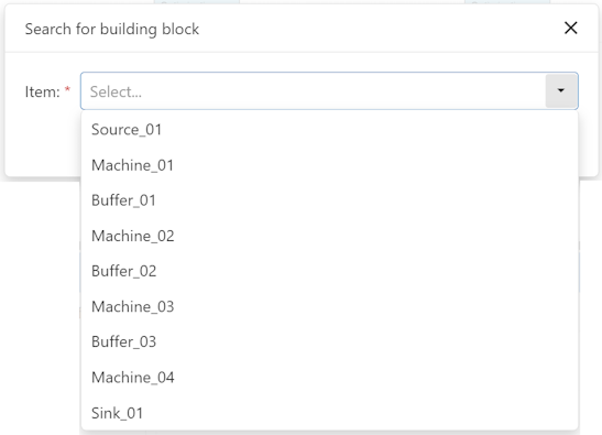
Figure 6 - Searching
Parameter display mode
Here the user can swtich between three display modes
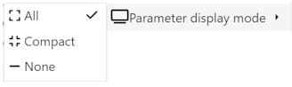
Figure 7 - Display modes
Print & Export
Here the model can be either printed, or exported as image or SVG. To export as image (*.png) or as SVG, simply select the corresponding entry in the dropdown.
A click on Print opens the print preview. Here, the current alternative can also be printed directly as a PDF.
It is also possible to have the width of the PDF to be generated calculated automatically depending on the aspect ratio of the project by activating the Dynamic width checkbox.
The button at the end of the page menu opens the system printer settings. The Print button can be used to print the selected alternative. The Cancel button can be used to switch back to the previous view.
Show toolbox
Here the toolbox can be shown/hidden by clicking the toggle button.
Tabular editor
Opens a tabular editor above the modeling surface where all parameters of all available objects can be edited at once (premium feature).
Search and filter options are also available - grey areas can not be filled.
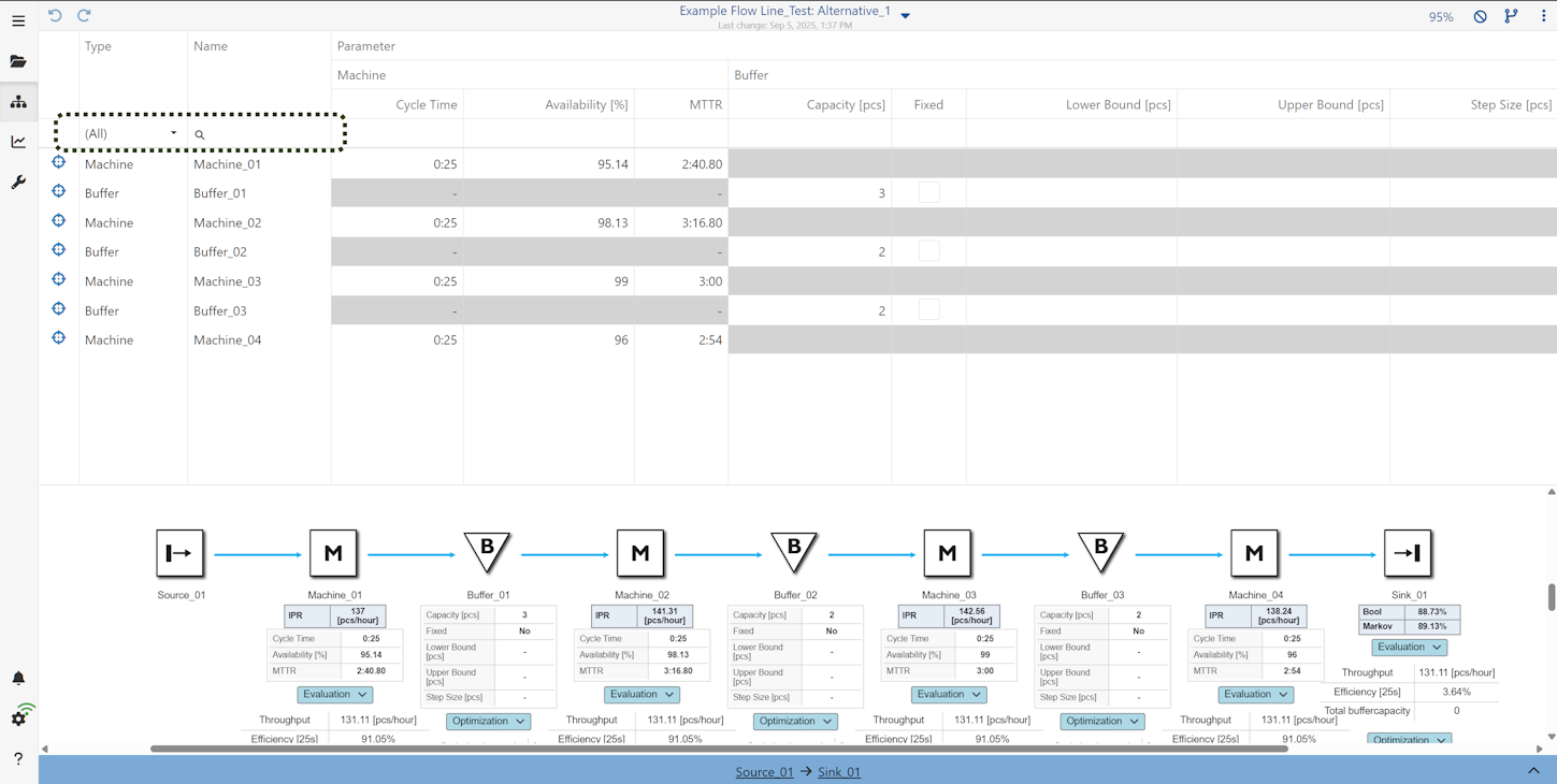
Figure 8 - Tabular editor
© SimPlan AG - Hanau District Court, Commercial Register (Part B) 6845 - info@simplan.de - www.simplan.de/en